Use this information for details about the controls, connectors, and LEDs.
The following illustration identifies the buttons, connectors, and LEDs on the control panel.
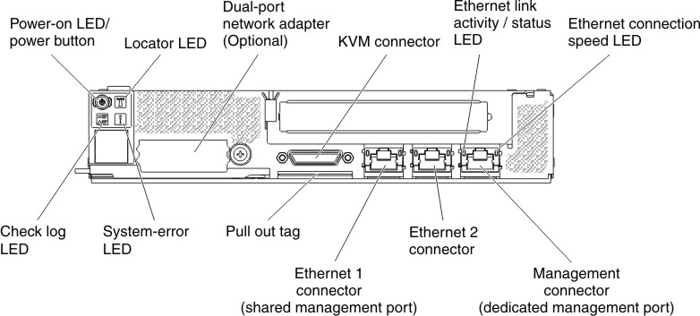
Figure 1. Compute node control panel buttons, connectors, and LEDs
- Power button/LED
- When the compute node is connected
to power through the IBM NeXtScale n1200 Enclosure, press this button to turn on or turn off the compute node. This button is also the power LED. This green LED indicates the power status of the compute node:
- Flashing rapidly: The LED flashes rapidly for the following
reasons:
- The compute node has been installed in a chassis. When you install the compute node, the LED flashes rapidly for up to 90 seconds while the integrated management module II (IMM2) in the compute node is initializing.
- The IBM NeXtScale n1200 Enclosure does not have enough power to turn on the compute node.
- The IMM2 in the compute node is not communicating with the Chassis Management Module.
- Flashing slowly: The compute node is connected to power through the IBM NeXtScale n1200 Enclosure and is ready to be turned on.
- Lit continuously: The compute node is connected to power through the IBM NeXtScale n1200 Enclosure and is turned on.
When the compute node is on, pressing this button causes an orderly shutdown of the compute node so that it can be removed safely from the chassis. This includes shutting down the operating system (if possible) and removing power from the compute node.
If an operating system is running, you might have to press the button for approximately 4 seconds to initiate the shutdown.
Attention: Pressing the button for 4 seconds forces the operating system to shut down immediately. Data loss is possible. - Flashing rapidly: The LED flashes rapidly for the following
reasons:
- Locator LED
- The system administrator can remotely light this blue LED to aid in visually locating the compute node.
- Check log LED
- When this yellow LED is lit, it indicates that a system error has occurred. Check the Event logs for additional information.
- System error LED
- When this yellow LED is lit, it indicates that a system error has occurred. A system-error LED is also on the rear of the server. An LED on the light path diagnostics panel on the operator information panel or on the system board is also lit to help isolate the error. This LED is controlled by the IMM.
- KVM connector
- Connect the console breakout cable to this connector (see Console breakout cable for more
information).Note: It is best practice to connect the console breakout cable to only one compute node at a time in each IBM NeXtScale n1200 Enclosure.
- Ethernet connectors
- Use either of these connectors to connect the server to a network. When you enable shared Ethernet for IMM2 in the Setup utility, you can access the IMM2 using either the Ethernet 1 or the system-management Ethernet (default) connector. See Using the Setup utility for more information.
- Ethernet link activity/status LED
- When any of these LEDs is lit, they indicate that the server is transmitting to or receiving signals from the Ethernet LAN that is connected to the Ethernet port that corresponds to that LED.
- Management connector
- Use this connector to connect the server to a network for full systems-management information control. This connector is used only by the Integrated Management Module II (IMM2). A dedicated management network provides additional security by physically separating the management network traffic from the production network. You can use the Setup utility to configure the server to use a dedicated systems management network or a shared network.