The following illustration shows the location and description of the switches and jumpers.
Figure 1. Location and description of switches and jumpers
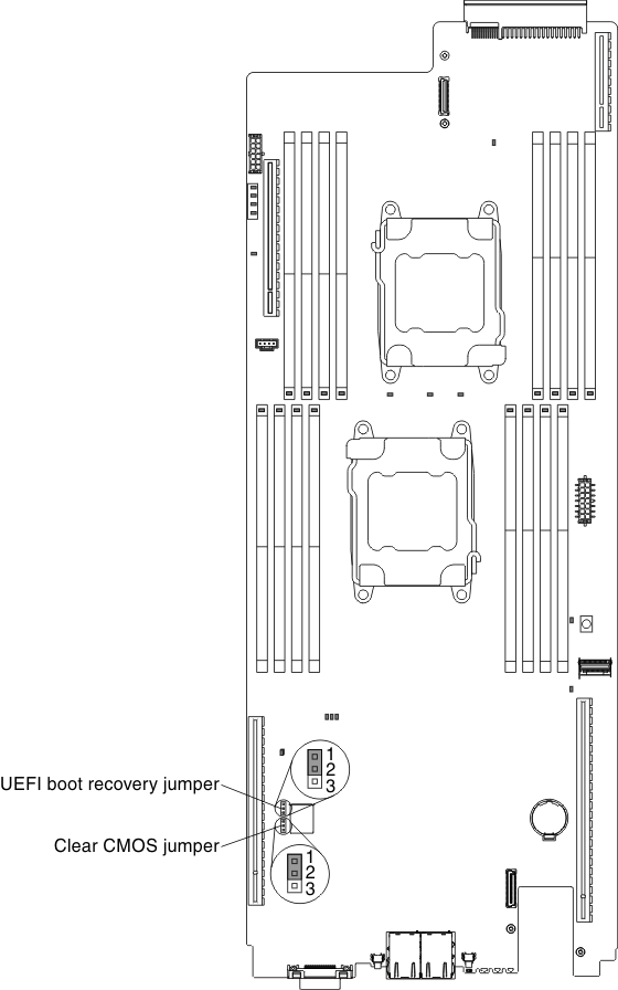
Note: If there is a clear protective sticker on the top of the
switch blocks, you must remove and discard it to access the switches.
Note:
- Before you change any switch settings or move any jumpers, turn off the server. Review the information in Safety, Installation guidelines, Handling static-sensitive devices, and Turning off the compute node.
- Any system-board switch or jumper block that is not shown in the illustrations in this document are reserved.
The following table describes the jumpers on the system board.
| Jumper name | Jumper setting |
|---|---|
| Clear CMOS jumper |
|
| UEFI boot recovery jumper |
|
|
Note:
|
|