The fan and power controller has LEDs, controls, and connectors that you can use to obtain status information and restart the fan and power controller.
Figure 1. Fan and power controller with call
outs for the LEDs, controls, and connectors
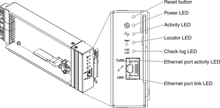
The fan and power controller has the following LEDs,
controls, and connectors:
- Power-on LED
- When this LED is lit (green), it indicates that the fan and power controller has power.
- Heartbeat LED
- When this LED is lit (green), it indicates that the fan and power controller is actively controlling the chassis.
- Locator LED
- When this LED is lit (blue), it indicates the chassis location in a rack.
- Check log LED
- When this LED is lit (yellow), it indicates that a system error has occurred. Check the event log for additional information.
- Ethernet port activity (RJ-45) LED
- When this LED is flashing (green), it indicates that there is activity through the remote management and console (Ethernet) port over the management network.
- Ethernet port link (RJ-45) LED
- When this LED is lit (green), it indicates that there is an active connection through the remote management and console (Ethernet) port to the management network.
- Remote management and console (Ethernet) connector
- The remote management and console connector (RJ-45) is the management network connector for all chassis components. This 10/100 base T Ethernet connector is usually connected to the management network through a top-of-rack switch.