Use this information to remove the manifold.
Read the safety information in Safety and Installation guidelines.
If you are replacing a server component or installing an optional device in the server, you need to slide the server out from the rack enclosure, turn off the server and peripheral devices, and disconnect the power cords and all external cables.
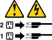
Attention: You must remove the power from the
rack cabinet and all components before you connect or disconnect the
water supply lines and drain or fill the manifold.
Statement
5

CAUTION:
The power control button on the device and the power
switch on the power supply do not turn off the electrical current
supplied to the device. The device also might have more than one power
cord. To remove all electrical current from the device, ensure that
all power cords are disconnected from the power source.
DWC Safety
Information, Statement 14

CAUTION:
The water might cause irritation to the skin and eyes. Avoid direct contact with the lubricant.
(C034)
Attention: Ensure proper handling procedures are followed when
working with any chemically treated water used in the compute rack
cooling system. Ensure that material safety data sheets (MSDS) and
safety information are provided by the water chemical treatment supplier
and that proper personal protective equipment (PPE) is available as
recommended by the water chemical treatment supplier. Protective gloves
and eyewear may be recommended as a precaution.
To remove the manifold, complete the following steps.
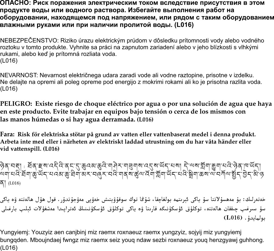
- At the front of the rack, close both Eaton ball valves.
Figure 1. Eaton ball valves closed
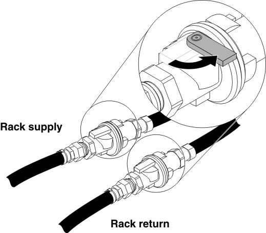
- Remove EMC shields on both sides of the top chassis.
Figure 2. EMC shields removal
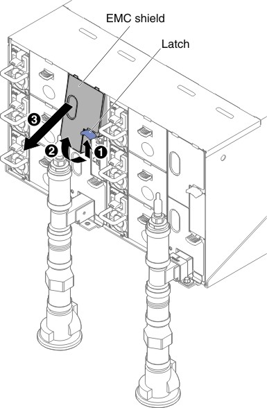
Figure 3. EMC shields removal
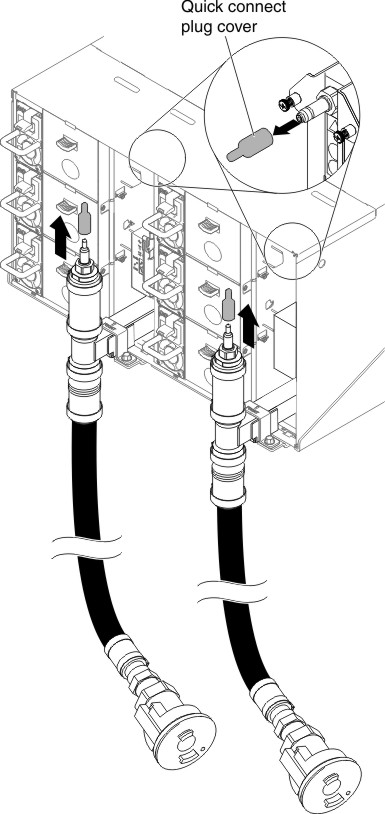
- Remove the red quick connect plug covers from the tops
of each manifold.
Figure 4. Quick connect plug covers removal
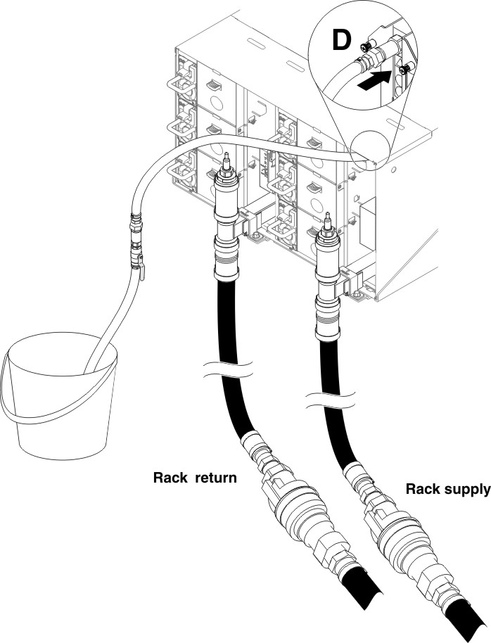
- Place the open blue hose end of the drain hose (tool left
at customer site) into a bucket. Make sure that the lever on the drain
hose valve is closed (lever is pointed away from the hose).
Figure 5. Water draining
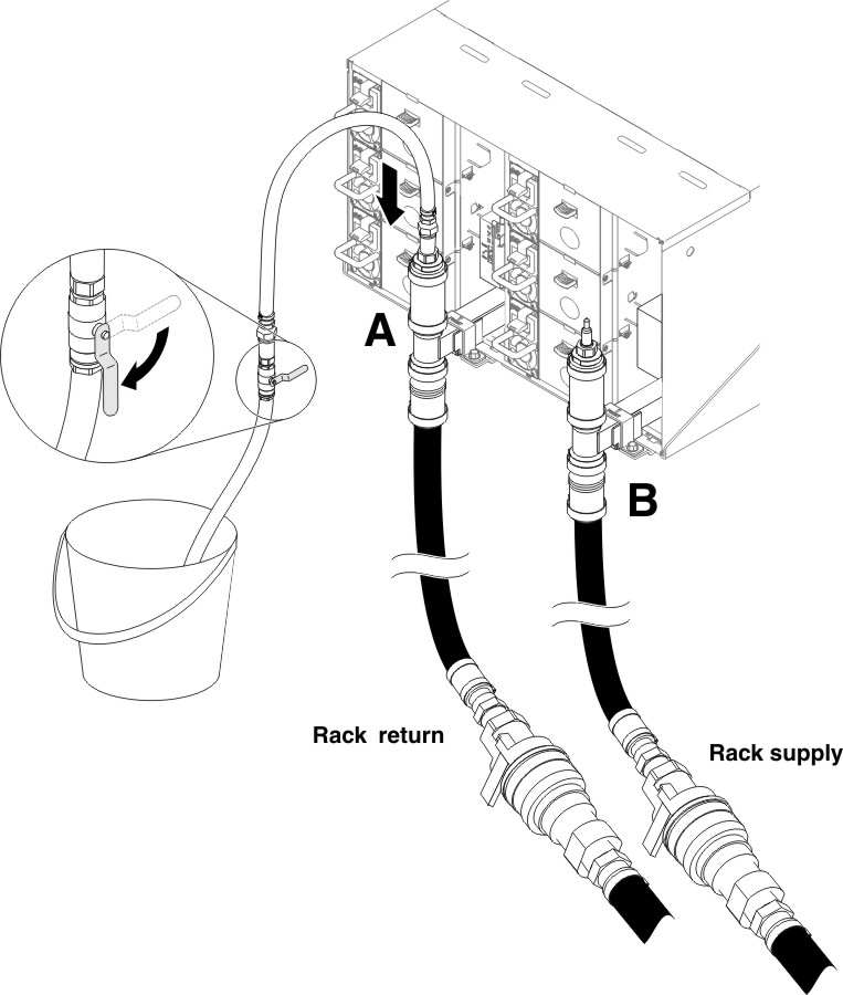
- Connect the Quick connect socket from the drain hose tool
to the top of the return side manifold (position middle of the rack).
Figure 6. Quick connect socket from the drain hose tool to the top of the return side manifold connection
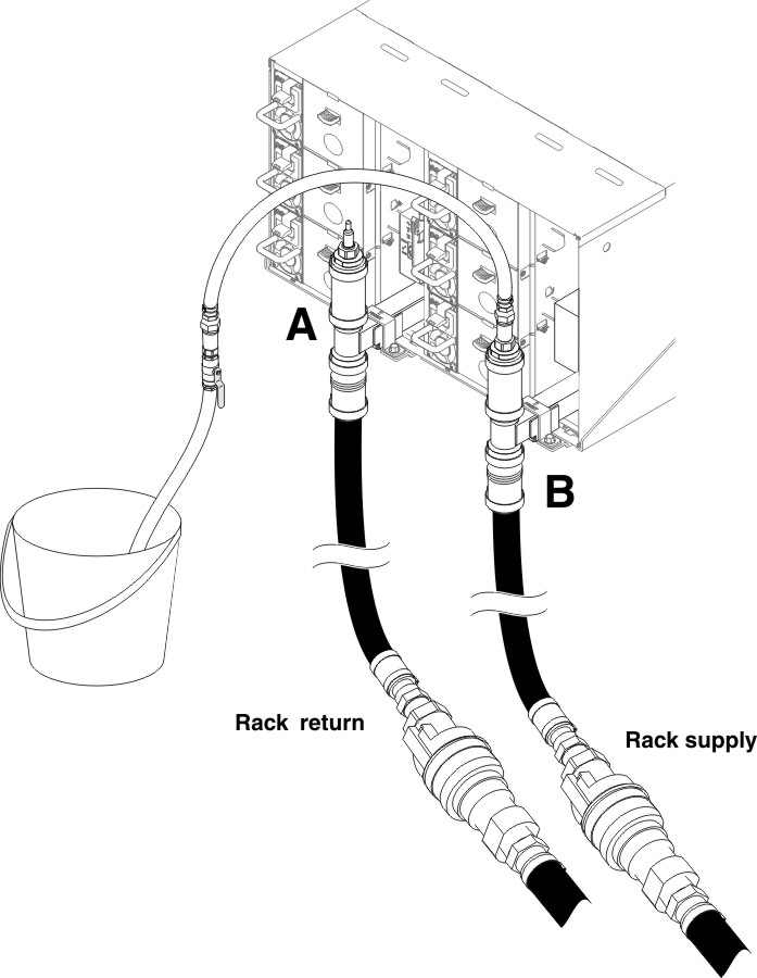
- Once the quick connect is attached, slowly open the hose
valve and allow water to drain until water stops flowing (approximately
1 minute).
Figure 7. Water draining
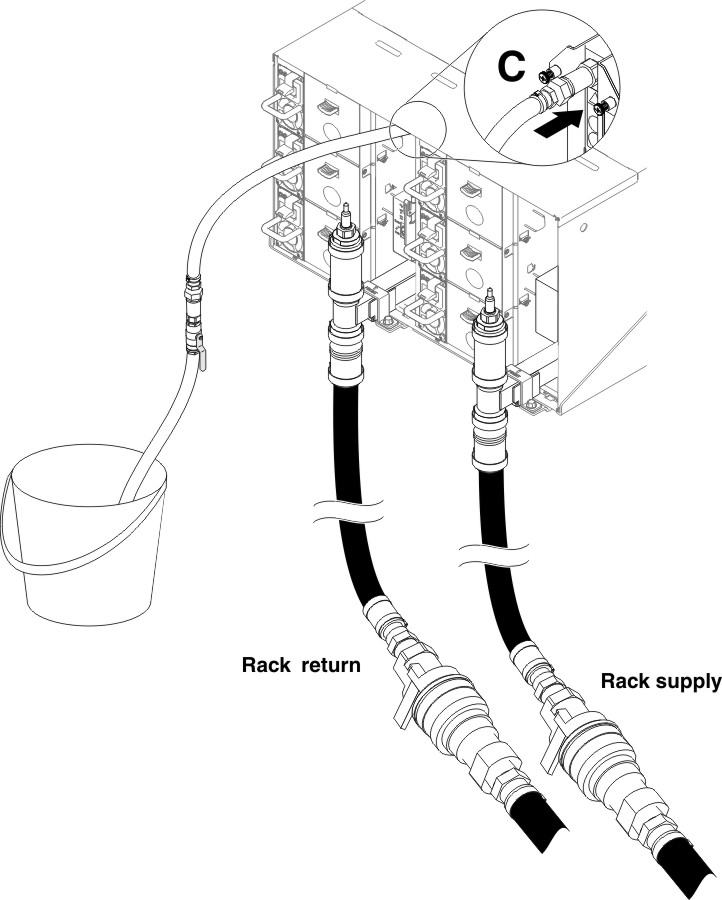
- Move to the top position of the other manifold (position
closest to the rack side wall). Leave the hose connected to the top
of the manifold until water stops flowing. Disconnect quick connect
from top of manifold.
Figure 8. Quick connect socket from the drain hose tool to the top of the supply side manifold connection
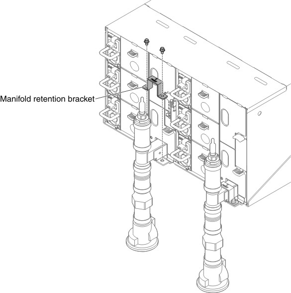
- Move to the rear of the rack. Remove manifold retention
bracket that is retaining the manifold (top chassis position only).
Figure 9. Retention bracket removal
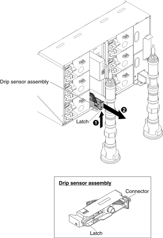
- Remove drip sensor assembly. Lift latch upwards.
Figure 10. Drip sensor assembly removal
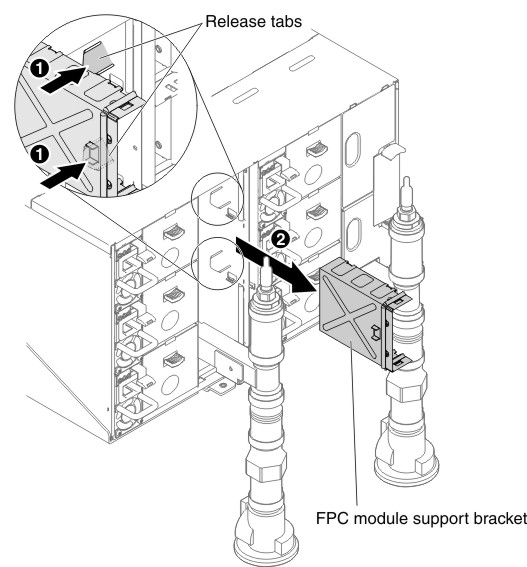
- Remove FPC card module and FPC card module support bracket
if portion of left manifold is being replaced. If it is the right
side manifold, remove blank filler.
Figure 11. FPC card module removal
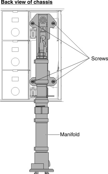
- Unscrew 4 screws (using the screwdriver contained in the
manifold repair kit) to loosen the manifold bracket from the chassis.
Figure 12. Manifold screw locations
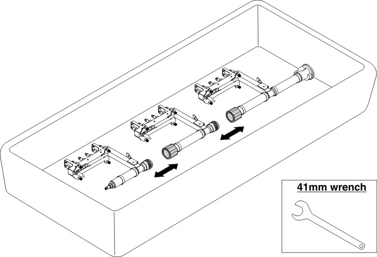
- Place a pan under the section of the manifold to be removed.
Figure 13. Manifold disassemble