The following notes describe the type of microprocessor that the server supports and other information that you must consider when you install a microprocessor and heat sink.
Before you replace a microprocessor and heat sink, complete
the following steps:
- Read Safety and Installation guidelines.
- If the compute node is installed in a NeXtScale n1200 Enclosure, remove it (see Removing a compute node from a chassis for instructions).
- Carefully lay the compute node on a flat, static-protective surface, orienting the compute node with the bezel pointing toward you.
- Thermal grease can be stayed on a heat sink for 2 years. Check the manufacturing date on the new heat sink and if is over 2 years, you need to remove the older grease from a heat sink and re-grease it to avoid seating issues. See Thermal grease for more information.
- Microprocessors are to be installed only by trained technicians. Important: Always use the microprocessor installation tool to install a microprocessor. Failing to use the microprocessor installation tool may damage the microprocessor sockets on the system board. Any damage to the microprocessor sockets may require replacing the system board.
- Be extremely careful, the microprocessor socket contacts are very fragile. Do not touch the microprocessor socket contacts. Contaminants on the microprocessor contacts or microprocessor socket contacts, such as oil from your skin, can cause connection failures between the contacts and the socket.
- Do not allow the thermal grease on the microprocessor and heat sink to come in contact with anything. Contact with any surface can contaminate the thermal grease and the microprocessor socket.
- Do not use any tools or sharp objects to lift the locking levers on the microprocessor socket. Doing so might result in permanent damage to the system board.
- Each microprocessor socket must always contain either a socket cover or a microprocessor and heat sink.
- Be sure to use only the installation tools provided with the new microprocessor to remove or install the microprocessor. Do not use any other tool.
- When installing multiple microprocessors, open one microprocessor socket at a time to avoid damaging other microprocessor socket contacts.
- The microprocessor installation tool has the microprocessor installed
on the tool, and may have a protective cover over the microprocessor.
Do not use the tool, or remove the cover until you are instructed
to do so.Note: Be sure to use the installation tool that comes with your microprocessor installation tool assembly.
- The server supports up to two multi-core microprocessors. See the Lenovo ServerProven website for a list of supported microprocessors.
- The first microprocessor must always be installed in microprocessor socket 1 on the system board.
- When one microprocessor is installed, the air baffle must be installed to provide proper system cooling.
- Do not remove the first microprocessor from the system board when you install the second microprocessor.
- When you install the second microprocessor, you must also install additional memory, the fourth and sixth fans. See Installing a memory module for details about the installation sequence.
- Do not mix microprocessors with different cores in the same server.
- To ensure proper server operation when you install an additional microprocessor, use microprocessors that have the same QuickPath Interconnect (QPI) link speed, integrated memory controller frequency, core frequency, power segment, internal cache size, and type.
- Mixing microprocessors of different stepping levels within the same server model is supported.
- When mixing microprocessors with different stepping levels within the same server model, you do not have to install the microprocessor with lowest stepping level and features in microprocessor socket 1.
- Both microprocessor voltage regulator modules are integrated on the system board.
- Read the documentation that comes with the microprocessor to determine whether you have to update the server firmware. To download the latest level of server firmware and other code updates for your server, go to the Fix Central website.
- The microprocessor speeds are automatically set for this server; therefore, you do not have to set any microprocessor frequency-selection jumpers or switches.
- If the thermal-grease protective cover (for example, a plastic
cap or tape liner) is removed from the heat sink, do not touch the
thermal grease on the bottom of the heat sink or set down the heat
sink. For more information about applying or working with thermal
grease, see Thermal grease. Note: Removing the heat sink from the microprocessor destroys the even distribution of the thermal grease and requires replacing the thermal grease.
- To order an additional optional microprocessor, contact your Lenovo sales representative or Lenovo reseller.
The installation tool has two settings for installing two
different sizes of microprocessors. The settings that are marked on
tool are L
for smaller low core microprocessors, and H
for larger high core microprocessors. Installation tool supports
the following families of microprocessors: E5-26xx, E5-46xx, E5-26xx
v2, E5-46xx v2.
To replace a microprocessor and heat sink, complete the following steps:
-
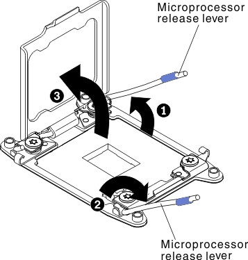
Open the microprocessor socket release levers and retainer:
Figure 1. Microprocessor socket levers and retainer disengagement
-
Install the microprocessor in the microprocessor socket:
-
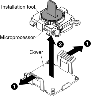
Remove the microprocessor protective cover if one is
present. The microprocessor is preinstalled on the installation tool.
Figure 2. Installation tool cover removal
-
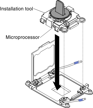
Align the installation tool with the microprocessor
socket. The installation tool rests flush on the socket only if properly
aligned.
Figure 3. Installation tool alignment
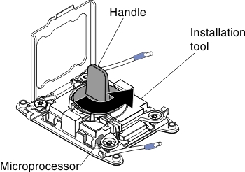
-
Twist the handle of the installation tool assembly counterclockwise
until the microprocessor is inserted into the socket, and lift the
installation tool out of the socket. The following illustration shows
the tool handle in the open position.
Figure 4. Installation Tool
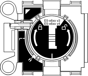
Figure 5. Installation tool handle adjustment
Attention:- Do not press the microprocessor into the socket.
- Make sure that the microprocessor is oriented and aligned correctly in the socket before you try to close the microprocessor retainer.
- Do not touch the thermal material on the bottom of the heat sink or on top of the microprocessor. Touching the thermal material will contaminate it.
-
Remove the microprocessor protective cover if one is
present. The microprocessor is preinstalled on the installation tool.
-
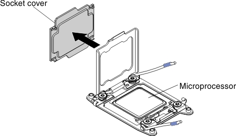
Remove the microprocessor socket cover,
tape, or label from the surface of the microprocessor socket, if one
is present. Store the socket cover in a safe place.
Figure 6. Socket cover removal
Attention: When you handle static-sensitive devices, take precautions to avoid damage from static electricity. For details about handling these devices, see Handling static-sensitive devices. -
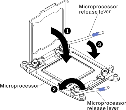
Close the microprocessor socket release levers and retainer:
Figure 7. Microprocessor socket levers and retainer engagement
-
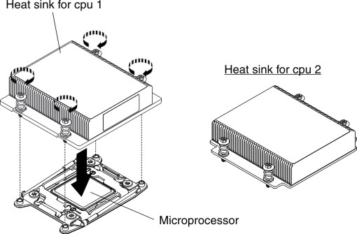
Install the heat sink.
Attention:
- Thermal grease can be stayed on a heat sink for 2 years. Check the manufacturing date on the new heat sink and if is over 2 years, you need to remove the older grease from a heat sink and re-grease it to avoid seating issues. See Thermal grease for more information.
- Do not set down the heat sink after you remove the plastic cover.
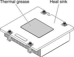
- Do not touch the thermal grease on the bottom of the heat sink
after you remove the plastic cover. Touching the thermal grease will
contaminate it. See Thermal grease for more information. Figure 8. Thermal grease
-
Position the heat sink over the microprocessor. The
heat sink is keyed to assist with proper alignment.
Figure 9. Heat sink installation