Use this information to remove a microprocessor.
The following notes describe the type of microprocessor that the server supports and other information that you must consider when you install a microprocessor and heat sink:
- The server supports one Intel land grid array (LGA) 1150 dual-core or quad-core microprocessor. The type, speed, and L3 cache of the microprocessor depends on the server model.
- Read the documentation that comes with the microprocessor to determine whether you have to update the server firmware. To download the most current level of server firmware, go to the Lenovo Support Portal and the Fix Central website.
- The microprocessor uses an integrated voltage regulator on the system board.
- Microprocessors are to be installed only by trained technicians.
- Do not allow the thermal grease on the microprocessor and heat sink to come in contact with anything. Contact with any surface can compromise the thermal grease and the microprocessor socket.
- Dropping the microprocessor during installation or removal can damage the contacts.
- Do not touch the microprocessor contacts; handle the microprocessor by the edges only. Contaminants on the microprocessor contacts, such as oil from your skin, can cause connection failures between the contacts and the socket.
- The pins on the sockets are fragile. Any damage to the pins might require replacing the system board.
Read the safety information in Safety and Installation guidelines.
If you are replacing a server component in the water-cooled technology tray, you need to remove the water-cooled technology tray from the chassis enclosure and refer to the Removing a water-cooled technology tray from a chassis and Installing a water-cooled technology tray in a chassis sections.
To remove a microprocessor, complete the following steps.
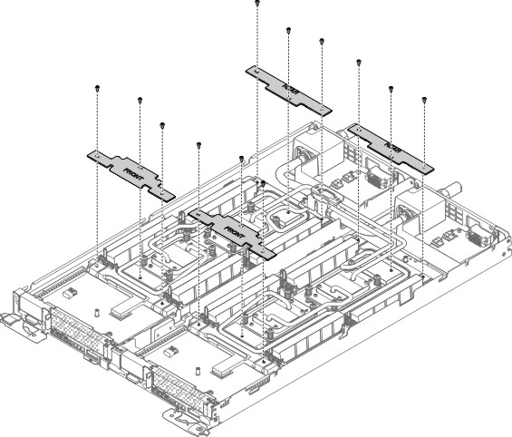
- Remove the front and rear clamp plates.
Figure 1. Water Loop retention brackets removal
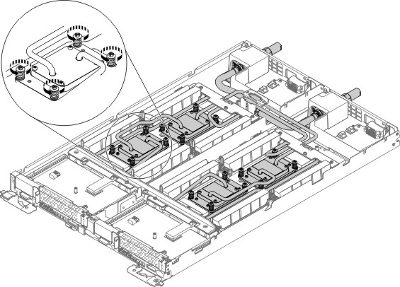
- Loosen cold plate captive screws (16 screws).
Figure 2. Loosen cold plate captive screws
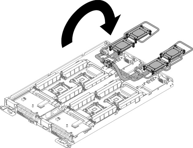
- Rotate the water loop back over the power boards.
Figure 3. Water loop rotated
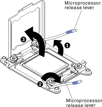
- Open the microprocessor socket release levers and retainer.
Figure 4. Microprocessor socket levers and retainer disengagement
- Remove the microprocessor from the socket.
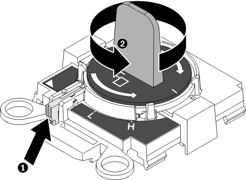
- Select the empty installation tool and ensure that the
handle is in the open position. If the installation tool handle is
not in the open position, 1lift the interlock latch and hold
it up while you2twist the microprocessor installation tool
handle counterclockwise to the open position, and then release the
interlock latch. The following illustration of the installation tool
shows the location of the interlock latch and counterclockwise rotation
of the handle before loading the microprocessor.
Figure 5. Installation tool handle adjustment
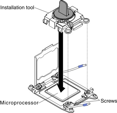
- Align the installation tool with the screws, as shown
in the following graphic, and lower the installation tool on the microprocessor.
The installation tool rests flush on the socket only when it is aligned
correctly.
Figure 6. Microprocessor installation
- Gently twist the handle of the installation tool clockwise
until it locks in the
H
orL
position, depending on the size of microprocessor, and then lift the microprocessor out of the socket.Figure 7. Installation tool handle adjustment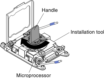
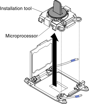
- Lift the microprocessor out of the socket.
Figure 8. Microprocessor removal
- Select the empty installation tool and ensure that the
handle is in the open position. If the installation tool handle is
not in the open position, 1lift the interlock latch and hold
it up while you2twist the microprocessor installation tool
handle counterclockwise to the open position, and then release the
interlock latch. The following illustration of the installation tool
shows the location of the interlock latch and counterclockwise rotation
of the handle before loading the microprocessor.
If you are instructed to return the server component or optional device, follow all packaging instructions, and use any packaging materials for shipping that are supplied to you.