Use this information to replace a copper water loop.
Attention:
- Copper water loop supports Intel Xeon E5-2600 v3 and v4 series.
- Copper water loop is to be installed only by trained technicians.
- Make sure the water loop of the microprocessors are properly greased.
- The copper water loop FRU is packaged with the protective bracket on the top.
- If reusing the water loop apply new grease using the 9 dot method.
- Do not set down the water loop after you remove the four plastic covers.
- Do not touch the microprocessor contacts; handle the microprocessor by the edges only. Contaminants on the microprocessor contacts, such as oil from your skin, can cause connection failures between the contacts and the socket.
- The pins on the sockets are fragile. Any damage to the pins might require replacing the system board.
Read the safety information in Safety and Installation guidelines.
If you are replacing a server component in the water-cooled technology tray, you need to remove the water-cooled technology tray from the chassis enclosure and refer to the Removing a water-cooled technology tray from a chassis and Installing a water-cooled technology tray in a chassis sections.
To install a copper water loop, complete the following steps.
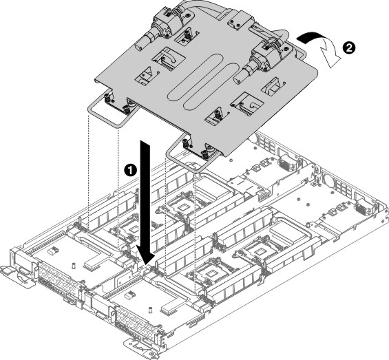
- Align and place the copper water loop on the pocket of
the wall which is parallel to the front side of the planar tray.
Figure 1. Copper water loop installation
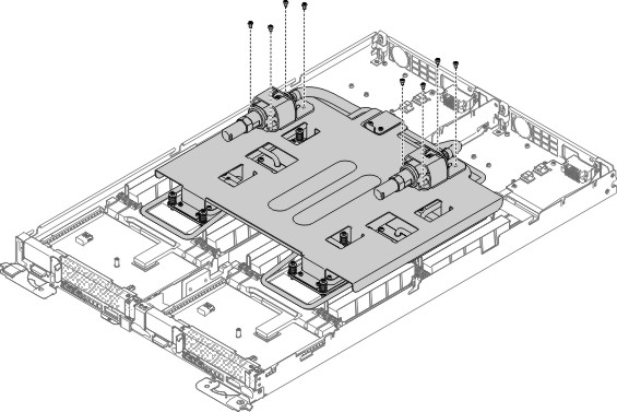
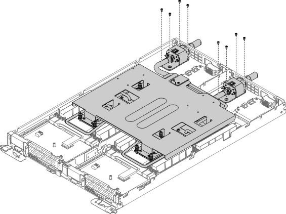
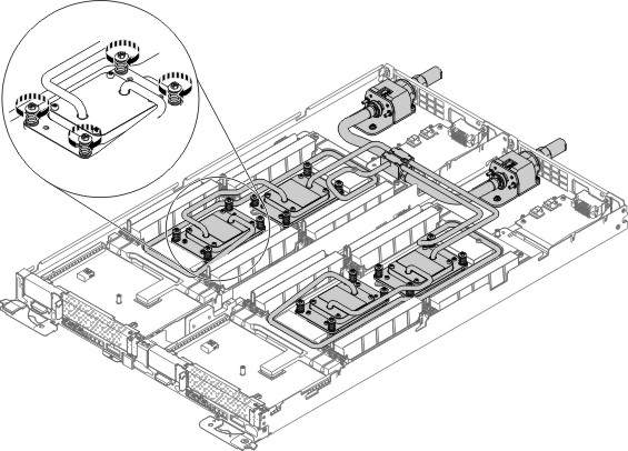
- Remove quick connection assembly screws (8 screws) from
the water loop.
Figure 2. Quick connection assembly screws removal
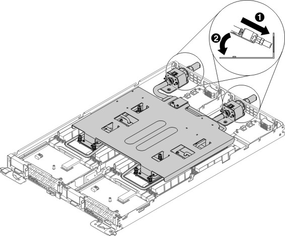
- Hook two quick connect assemblies to the planar tray.
Figure 3. Quick connect assemblies installation
- Install 8 quick connect assembly screws into the planar
tray.
Figure 4. 8 quick connect assembly screws installation
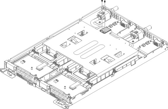
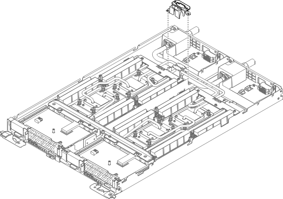
- Remove the junction block support plate (2 screws).
Figure 5. Junction block support plate removal
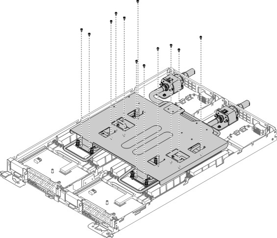
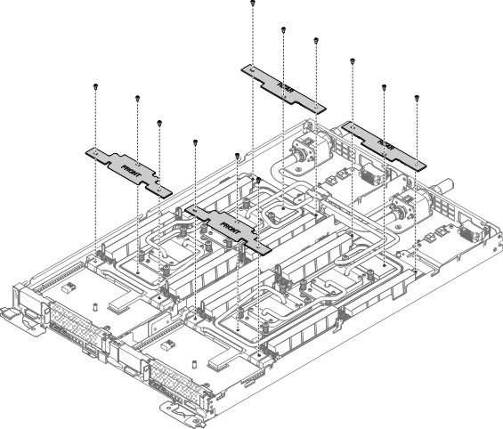
- Remove the 12 screws from the copper water loop protective
bracket.
Figure 6. 12 screws from the copper water loop protective bracket removal
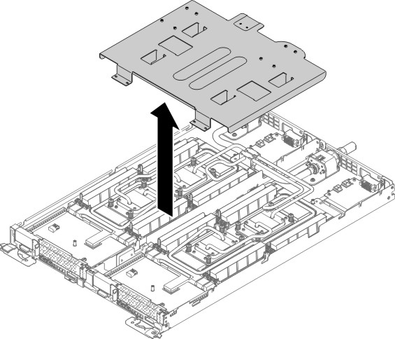
- Remove the copper water loop protective bracket.
Figure 7. Copper water loop protective bracket removal
- Press firmly on the 16 microprocessor screws and tighten
them with a screwdriver, alternating among the screws until they are
tight. If possible, each screw should be rotated two full rotations
at a time. Repeat until the screws are tight. Do not overtighten the
screws by using excessive force. If you are using a torque wrench,
tighten the screws to 1.0 to 1.2 Newton-meters (Nm) (8.85 to 10.6
inch-pounds).
Figure 8. Tighten cold plate captive screws
- Install the front and rear clamp plates. (12 screws).
Figure 9. Clamp plates installation
- Install the junction block retention bracket.
Figure 10. Junction block retention brackets installation
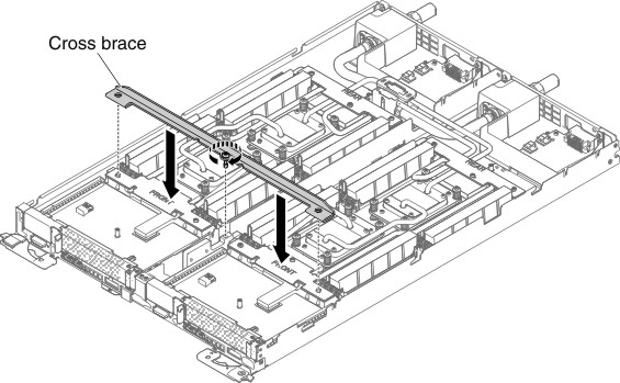
- Reinstall the cross brace using M4 screw.
Figure 11. Cross brace installation