Use this information to replace a microprocessor.
The following notes describe the type of microprocessor that the server supports and other information that you must consider when you install a microprocessor and water loop:
- Microprocessors are to be installed only by trained technicians.
Important: Always use the microprocessor installation tool to install a microprocessor. Failing to use the microprocessor installation tool may damage the microprocessor sockets on the system board. Any damage to the microprocessor sockets may require replacing the system board.
- The server supports up to four Intel® Xeon™ E5-2600 v4 series multi-core microprocessors. See the IBM ServerProven website for a list of supported microprocessors.
- Do not mix microprocessors with different cores in the same server.
- All four microprocessor must always be installed in microprocessor sockets on the system board.
- When microprocessors are installed, the air baffle must be installed to provide proper system cooling.
- When you install the second microprocessor, you must also install additional memory. See Memory module installation for details about the installation sequence.
- To ensure proper server operation when you install an additional microprocessor, use microprocessors that have the same QuickPath Interconnect (QPI) link speed, integrated memory controller frequency, core frequency, power segment, internal cache size, and type.
- Mixing microprocessors of different stepping levels within the same server model is supported.
- When mixing microprocessors with different stepping levels within the same server model, you do not have to install the microprocessor with lowest stepping level and features in microprocessor socket 1.
- Both microprocessor voltage regulator modules are integrated on the system board.
- Read the documentation that comes with the microprocessor to determine whether you have to update the server firmware. To download the latest level of server firmware and other code updates for your server, go to the Lenovo Support Portal.
- The microprocessor speeds are automatically set for this server; therefore, you do not have to set any microprocessor frequency-selection jumpers or switches.
- To order an additional optional microprocessor, contact your Lenovo sales representative or Lenovo reseller.
- Microprocessors are to be installed only by trained technicians.
- Do not allow the thermal grease on the microprocessor and water loop to come in contact with anything. Contact with any surface can compromise the thermal grease and the microprocessor socket.
- Dropping the microprocessor during installation or removal can damage the contacts.
- Do not touch the microprocessor contacts; handle the microprocessor by the edges only. Contaminants on the microprocessor contacts, such as oil from your skin, can cause connection failures between the contacts and the socket.
- The pins on the sockets are fragile. Any damage to the pins might require replacing the system board.
Read the safety information in Safety and Installation guidelines.
If you are replacing a server component in the water-cooled technology tray, you need to remove the water-cooled technology tray from the chassis enclosure and refer to the Removing a water-cooled technology tray from a chassis and Installing a water-cooled technology tray in a chassis sections.
To install a microprocessor and water loop, complete the following steps.
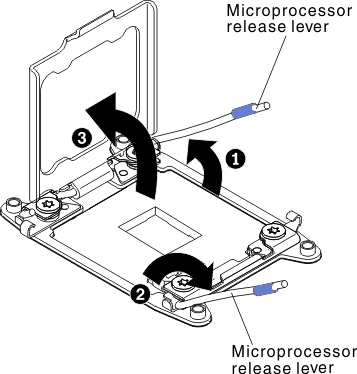
- Open the microprocessor socket release levers and retainer:
Figure 1. Microprocessor socket levers and retainer disengagement
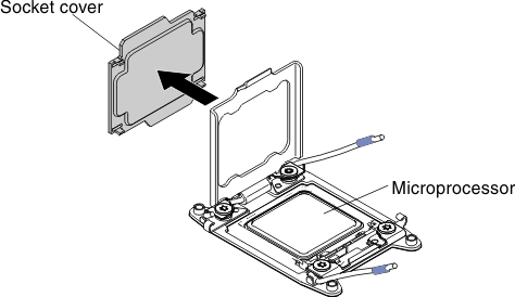
- Remove the microprocessor socket cover,
tape, or label from the surface of the microprocessor socket, if one
is present. Store the socket cover in a safe place.
Figure 2. Socket cover removal
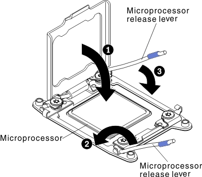
Attention: When you handle static-sensitive devices, take precautions to avoid damage from static electricity. - Close the microprocessor socket release levers and retainer:
Figure 3. Microprocessor socket levers and retainer engagement